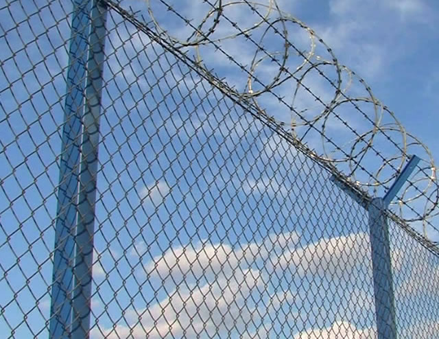
We supply aluminuminum coated steel chain link fences and gates for airport security projects. This aluminum coated chain link type wire mesh fence system is made of ASTM A491, Type I, Aluminuminum-coated steel wire, fence fabric woven of 9 gauge wire in 50 mm mesh, fabric twisted woven and barbed on the top selvage and knuckled on the bottom selvage. Metal posts for chain link fence are FS RR-F-191/3 line posts for end, corner, and pull posts. Barbed Wire 12.5 gauge aluminum-coated steel wire, with 4-point barbs is mounted along fence top commonly in 3 strands, for high security.
Technical specifications applied:
Wire diameter range: Min 1.628 mm (14 GA), Max 4.9mm (6 Ga)
Wire material: Aluminuminized, Aluminum, galvanized, and PVC coated wire.
Mesh size range:
Small mesh size: 19.05mm x 25.4mm x 31.75mm +/- 0.5%
Medium mesh size: 38.01 mm x 44.45mm +/- 0.5%
Standard: 50.8mm x 53.975 mm x 57.15 mm x 60.325 mm x 63.5 mm +/- 0.5%
Salvage Types: knuckle-knuckle, barb-knuckle, or barb-barb
Standard Roll sizes 50’
High-security Chain Link Fences and Gates:
High-security Chain-link Fence, Aluminuminum Coated
Motorized Cantilever Slide Gate
Made of ASTM A491, Type I, Aluminuminum-coated steel wire.
Fence fabric of 9 gauge wire woven in 50 mm mesh conforming to ASTM A116.
Fabric twisted woven and barbed on the top selvage and knuckled on the bottom selvage.
The mesh fabric is secured to posts using stretcher bars or ties spaced 375 mm on center, or by integrally weaving to integral fastening loops of end, corner, pull, and gate posts for full length of each post.
Metal Posts for Chain Link Fence
Metal posts for chain link fence shall conform to the requirements of ASTM F1043 or ASTM F1083. FS RR-F-191/3 line posts: End, corner, and pull posts. Galvanized tubular steel pipe shall conform to the requirements of Group IA.
Miscellaneous steel fittings and hardware for use with Aluminuminum-coated steel fabric shall be of commercial grade steel or better quality, wrought or cast as appropriate to the article, and sufficient in strength to provide a balanced design when used in conjunction with fabric posts, and wires of the quality specified herein. All steel fittings and hardware shall be protected with a zinc coating applied in conformance with ASTM A153/A153M. Barbed wire support arms shall withstand a load of 113 kg applied vertically to the outermost end of the arm.
Conforming to the requirements of ASTM F1043 or ASTM F1083, Braces, top rail and bottom rail.
Wire Ties
Submit samples as specified. FS RR-F-191/4.
Wire ties are made of the same material as the fencing fabric.
Barbed Wire 12.5 gauge
Barbed wire is constructed conforming to ASTM A121 Class II Aluminuminum-coated, 12.5 gauge wire with 14 gauge, round, 4-point barbs spaced no more than 125 mm apart.
Tension Wire
Wire ties for use in conjunction with a given type of fabric shall be of the same material and coating weight identified with the fabric type. Tension wire shall be 7-gauge marcelled steel wire with the same coating as the fabric type and shall conform to ASTM A824. Material conforming to FS RR-F-191/4.
MARKING
Each roll of mesh fabric carries a tag showing the kind of base metal (steel, Aluminuminum, or Aluminuminum alloy number), kind of coating, the gauge of the wire, the length of fencing in the roll, and the name of the manufacturer. Posts, wire, and other fittings are identified as to manufacturer, kind of base material (steel, Aluminuminum, or Aluminuminum alloy number), and kind of coating.
Gate Assembly
Quality conforming to ASTM F900 and/or ASTM F1184. Gate frames conforming to strength and coating requirements of ASTM F1083. Gate frames conforming to strength and coating requirements of ASTM F1043. Gate fabric the same specified for chain link fabric.
Gate Leaves
For gate leaves, more than 2.44 m wide, we provide intermediate members and diagonal truss rods or tubular members as necessary to provide rigid construction, free from sag or twist.
Gate leaves less than 2.44 m wide, truss rods or intermediate braces are supplied.
Intermediate braces supplied on all gate frames with an electro-mechanical lock.
Gate
Hardware and Accessories are supplied for furnishing and installing latches, hinges, stops, keepers, rollers, and other hardware items as required for the operation of the gate.
For high security applications, each end member of gate frames is extended sufficiently above the top member to carry three strands of barbed wire in horizontal alignment with barbed wire strands on the fence.
GATE OPERATOR
For sliding gates. Electrical gate operators have a right angle gearhead instantly reversing motor with magnetic drum-type brake, friction disc clutch, reversing starter with thermal overload protection, and a chain-driven geared rotary-type automatic limit switch. Gears consist of a hardened steel machine cut worm and mating bronze gear. All gears and bearings shall operate in a bath of oil. Gate operators are equipped with emergency release mechanism.
ELECTRO-MECHANICAL LOCKS
Electro-mechanical locking devices for sliding gates and personnel gates shall be solenoid actuated such that the deadbolt retracts when the solenoid is energized and remains electrically retracted until the gate is closed. Provide continuous duty type solenoid, rated for 120V ac, 60Hz operation. The locking device shall be unlockable by key and keyed on both sides. Status of the electro-mechanical lock shall be monitored by two limit switches (integral to the locking device) wired in series. One switch shall monitor the deadlock lever and the other monitor the locking tongue.
Installation conforming to ASTM F567.
Site clearing before installation:
Area on either side of the fence line shall be cleared to the extent indicated.
Space line posts equidistant at intervals not exceeding 3 m.
Terminal (corner, gate, and pull) posts shall be set at abrupt changes in vertical and horizontal alignment.
Excavation Clear all post holes of loose material. Spread waste material where directed. Eliminate ground surface irregularities along the fence line to the extent necessary to maintain a 25 mm clearance between the bottom of the fabric and finish grade.
POST INSTALLATION
All posts are set in concrete at the required dimension and depth and at the set spacing.
Posts should be spaced not more than 3 m apart and should be set at a minimum of 1 m in concrete footings. The post holes shall be in proper alignment so that there is a minimum of 75 mm of concrete on all sides of the posts. The concrete shall be thoroughly compacted around the posts by vibrating and shall have a smooth finish slightly higher than the ground and sloped to drain away from the posts. All posts shall be set plumb and to the required grade and alignment. No materials shall be installed on the posts, nor shall the posts be disturbed in any manner within seven (7) days after the individual post footing is completed. Should rock be encountered at a depth less than the planned footing depth, a hole shall be filled with grout, composed of one part Portland cement and two parts mortar sand. Any remaining space above the rock shall be filled with concrete in the manner described above. In lieu of drilling, the rock may be excavated to the required footing depth. No extra compensation shall be made for rock excavation.
RAILS
Horizontal brace rails, with diagonal truss rods and turnbuckles, shall be installed at all terminal posts.
WIRE FENCE FABRIC INSTALLATION
a. Install chain link fabric on the side of the post indicated. Attach fabric to terminal posts with stretcher bars and tension bands. Space bands at approximately 381 mm intervals. Install fabric and pull taut to provide a smooth and uniform appearance free from sag, without permanently distorting the fabric diamond or reducing the fabric height. Fasten fabric to line posts at approximately 381 mm intervals and fastened to all rails and tension wires at approximately 610 mm intervals.
b. Cut fabric by untwisting and removing pickets. Accomplish splicing by weaving a single picket into the ends of the rolls to be joined. The bottom of the installed fabric shall be 50 mm plus or minus 13 mm above the ground.
c. After the fabric installation is complete, exercise the fabric by applying a 222 newtons push-pull force at the center of the fabric between posts; the use of a 133 newtons pull at the center of the panel shall cause fabric deflection of not more than 63.5 mm when pulling fabric from the post side of the fence; every second fence panel shall meet this requirement; resecure and retest all failed panels at the Contractor's expense.
SUPPORTING ARMS
Install barbed wire supporting arms and barbed wire as indicated on the drawings and as recommended by the manufacturer. Anchor supporting arms to the posts in a manner to prevent easy removal with hand tools. Pull barbed wire taut and attach to the arms with clips or other means that will prevent easy removal.
GATE INSTALLATION
a. Install gates at the locations shown. Mount gates to swing as indicated. Install latches, stops, and keepers as required. Install gates as recommended by the manufacturer.
c. Submit 6 copies of operating and maintenance instructions, a minimum of 2 weeks prior to field training. Operating instructions shall outline the step-by-step procedures required for system startup, operation, and shutdown. Include the manufacturer's name, model number, service manual, parts list, and brief description of all equipment and their basic operating features. Include in the maintenance instructions routine maintenance procedures, possible breakdowns and repairs, and troubleshooting guide. Also include the general gate layout, equipment layout and simplified wiring and control diagrams of the system as installed.
GROUNDING
Ground fencing as specified. Electrical ground shall be constructed where a power line passes over the fence at 150 m intervals. The ground shall be installed directly below the point of crossing. The ground shall be accomplished with a copper clad rod 2.5 m long and a minimum of 19 mm in diameter driven vertically until the top is 152 mm below the ground surface. A No. 6 solid copper conductor shall be clamped to the rod and to the fence in such a manner that each element of the fence is grounded. Installation of ground rods shall not constitute a pay item and shall be considered incidental to fence construction. The Contractor shall comply with FAA-STD-019, paragraph 4.2.3.8 when fencing is adjacent to FAA facilities.
Chain Link Security Fencing Drawings
Chain Link Security Fence with Fastening Details
Single Cantilevered Slide Gate of Chain Link Fabric
